GEM GSMP-35A MAGNETOMETER
DESCRIPTION
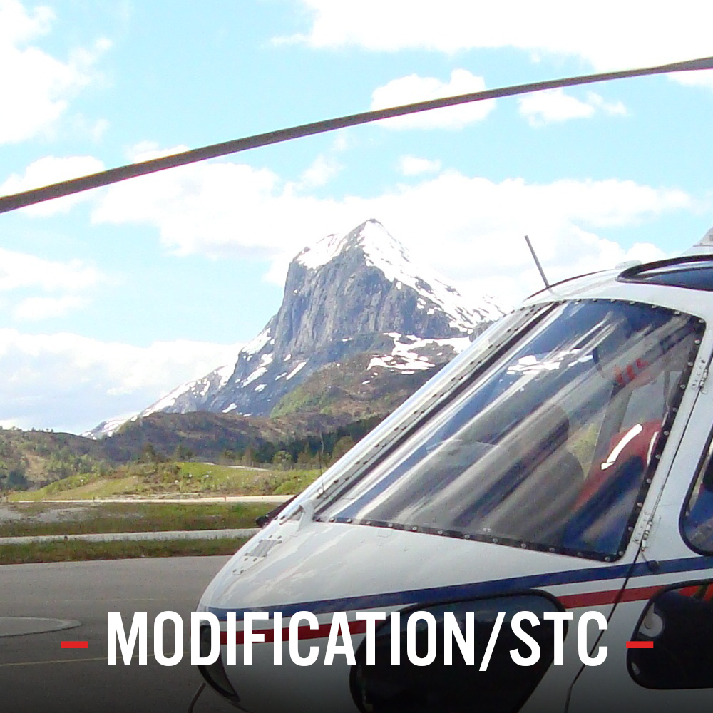
GEM GSMP-35 Gradiometer bird in flight
The GEM System GSMP-35A “Three axial Gradiometer/Magnetoemter” is part of Airlift’s Geophysical Equipment Installation STC for the AS350 helicopter, for airborne geophysical exploration and geological mapping. The STC includes as well different type of survey sensors (such as Radiation spectrometers, Electro-magnetometers, Magnetometers, Gradiometers, Cameras…) in different combinations to fit different typologies of survey missions. Over the years, a variety of different type/models of sensors has been added to the STC to meet requests of different customers.
The GSMP-35A magnetometer is a unique optically pumped Potassium sensor, high resolution Magnetometer, Vertical / Horizontal and Tri-Axial Gradiometer. The GSMP-35A gradiometer is attached under the helicopter cargo hook. The installation can be used with both cargo hook or the cargo swing. The use of the helicopter standard cargo hook installation instead of the cargo swing permits the installation of additional sensors under the helicopter belly, such as spectrometers or cameras.
The flexibility of this installation on the AS350 gives the possibility to use, during the same survey mission flight, multiple sensors, for example mounting a Gamma Ray spectrometer in the ventral frame and an electromagnetic sensor to the cargo sling.
Computers, data loggers and acquisition units associated to the externally mounted sensors, alongside with a keyboard and a foldable screen are installed in a dedicated computer rack mounted in the aft cabin.
The track information are given to the pilot using a 7-inch widescreen LCD display, or alternatively, a lightbar.
The rack is powered by a single point “Power Utility Outlet” on the cabin aft wall capable of up to 40A continuous load. The power is controlled via a dedicated on/off push button on the pilot’s console and status shown via a “Utility Power” indicator light on the instrument panel.
CONDITIONS & COMPATIBILITY LIMITATIONS
Before installation, the installer shall determine any possible conflict of this installation with other modifications already installed on the helicopter that may introduce adverse effect on airworthiness of the product or jeopardize flight safety.
INSTALLATION PLANNING
Varies depending configuration. Normally the fixed part of the installation (i.e. not removable, such as cut outs, power outlet…) are kept to a minimum. Installation of computers and sensors is performed through quick reconfigurations to minimize grounding time of the helicopter.
DOCUMENTATION DELIVERED
Approval Form, installation instructions, material list, drawings, wiring diagrams, instructions for continued airworthiness, rotorcraft flight manual supplement.
KIT
Different type of kit can be available on request (on the base of the customization of the installation).
The consumable materials required for the installation are not contained in the material kit and shall be ordered separately at vendors indicated in the material list.
APPROVAL
EASA STC Number 10032471 AS350 B, BA, B1, B2 and B3
Airlift AS is an EASA Part-21 Subp. J Approved Design Organisation (Approval No. EASA.21J.315).
DELIVERY
Delivery time for document package and for the Kit: Contact us
Download here our brochure
Contact us for more information